How to install alternative firmware to the SenseCAP M2 Data Only LoRaWAN Indoor Gateway
When I searched for a new LoRaWAN indoor gateway, my primary criterion was that it should be capable of running open-source firmware. The ChirpStack Gateway OS firmware caught my attention. It's based on OpenWrt and has regular releases. Its recent 4.7.0 release added support for the Seeed SenseCAP M2 Multi-Platform Gateway, which seemed like an interesting and affordable option for a LoRaWAN gateway.
Unfortunately, this device wasn't available through my usual suppliers. However, TinyTronics did stock the SenseCAP M2 Data Only, which looked to me like exactly the same hardware but with different firmware to support the Helium LongFi Network. Ten minutes before their closing time on a Friday evening, I called their office to confirm whether I could use it as a LoRaWAN gateway on an arbitrary network. I was helped by a guy who was surprisingly friendly for the time of my call, and after a quick search he confirmed that it was indeed the same hardware. After this, I ordered this Helium variant of the gateway.
Upon its arrival, the first thing I did after connecting the antenna and powering it on was to search for the Backup/Flash Firmware entry in Luci's System menu, as explained in Seeed Studio's wiki page about flashing open-source firmware to the M2 Gateway. Unfortunately, the M2 Data Only seemed to have a locked-down version of OpenWrt's Luci interface, without the ability to flash other firmware. There was no SSH access either. I tried to flash the firmware via TFTP, but to no avail..
After these disappointing attempts, I submitted a support ticket to Seeed Studio, explaining my intention to install alternative firmware on the device, as I wasn't interested in the Helium functionality. I received a helpful response by a field application engineer with the high-level steps to do this, although I had to fill in some details myself. After getting stuck on a missing step, my follow-up query was promptly answered with the missing information and an apology for the incomplete instructions, and I finally succeeded in installing the Chirpstack Gateway OS on the SenseCAP M2 Data Only. Here are the detailed steps I followed.
Initial serial connection
Connect the gateway via USB and start a serial connection with a baud rate of 57600. I used GNU Screen for this purpose:
When the U-Boot boot loader shows its options, press 0 for Load system code then write to Flash via Serial:
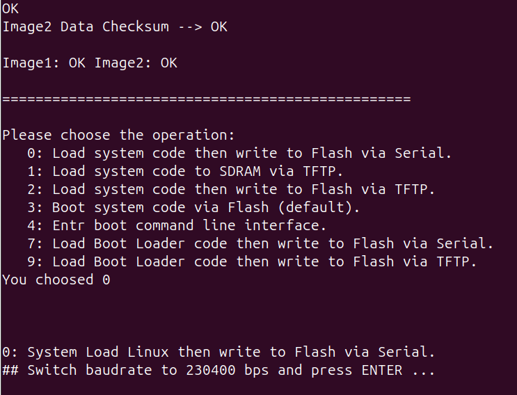
You'll then be prompted to switch the baud rate to 230400 and press ENTER. I terminated the screen session with Ctrl+a k and reconnected with the new baud rate:
Sending the firmware with Kermit
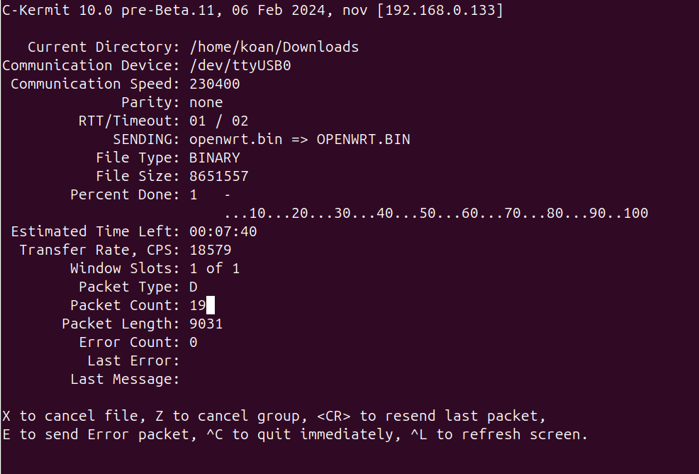
Upon pressing ENTER, you'll see the message Ready for binary (kermit) download to 0x80100000 at 230400 bps.... I never used the Kermit protocol before, but I installed ckermit and found the procedure in a StackOverflow response to the question How to send boot files over uart. After some experimenting, I found that I needed to use the following commands:
 koan@nov:~/Downloads$ kermit
C-Kermit 10.0 pre-Beta.11, 06 Feb 2024, for Linux+SSL (64-bit)
 Copyright (C) 1985, 2024,
  Trustees of Columbia University in the City of New York.
  Open Source 3-clause BSD license since 2011.
Type ? or HELP for help.
(~/Downloads/) C-Kermit>set port /dev/ttyUSB0
(~/Downloads/) C-Kermit>set speed 230400
/dev/ttyUSB0, 230400 bps
(~/Downloads/) C-Kermit>set carrier-watch off
(~/Downloads/) C-Kermit>set flow-control none
(~/Downloads/) C-Kermit>set prefixing all
(~/Downloads/) C-Kermit>send openwrt.bin
The openwrt.bin file was the firmware image from Seeed's own LoRa_Gateway_OpenWRT firmware. I decided to install this instead of the ChirpStack Gateway OS because it was a smaller image and hence flashed more quickly (although still almost 8 minutes).
After the file was sent successfully, I didn't see any output when reestablishing a serial connection. After responding this to Seeed's field application engineer, he replied that the gateway should display a prompt requesting to switch the baud rate again to 57600.
Kermit can also function as a serial terminal, so I just stayed within the Kermit command line and entered the following commands:
(~/Downloads/) C-Kermit>set speed 57600
/dev/ttyUSB0, 57600 bps
(~/Downloads/) C-Kermit>connect
Connecting to /dev/ttyUSB0, speed 57600
 Escapr character: Ctrl-\ (ASCII 28, FS): enabled
Type the escape character followed by C to get back,
or followed by ? to see other options.
----------------------------------------------------
## Total Size      = 0x00840325 = 8651557 Bytes
## Start Addr      = 0x80100000
## Switch baudrate to 57600 bps and press ESC ...
And indeed, there was the prompt. After pressing ESC, the transferred image was flashed.
Reboot into the new firmware
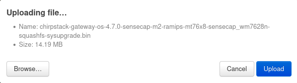
Upon rebooting, the device was now running Seeed's open-source LoRaWAN gateway operating system. Luci's menu now included a Backup/Flash Firmware entry in the System menu, enabling me to upload the ChirpStack Gateway OS image:
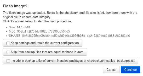
Before flashing the firmware image, I deselected the Keep settings and retain the current configuration option, as outlined in ChirpStack's documentation for installation on the SenseCAP M2:
Thus, I now have open-source firmware running on my new LoRaWAN gateway, with regular updates in place.