Using ESPHome on the Raspberry Pi Pico W and other RP2040 microcontroller boards
ESPHome is an open-source program that allows you to create your own home-automation devices using an ESP32, ESP8266, or RP2040 microcontroller board that you connect to LEDs, sensors, or switches. What sets ESPHome apart from other solutions like Arduino or MicroPython is that you don't need to program. Instead, you define your components and their respective pin connections in a YAML configuration file. ESPHome then generates the necessary C++ code and compiles it into firmware that you can install on the device. [1]
ESPHome is often used with ESP32 development boards. Support for the RP2040 platform, the chip in the popular Raspberry Pi Pico W, is still relatively new (introduced in ESPHome 2022.11). As a result, you may encounter some issues, some things are not clearly documented, and there aren't that many ESPHome example configurations using the RP2040. In this article, I'll share my findings after exploring ESPHome's RP2040 support.
Use the dashboard, not the wizard
A first issue you may encounter is that ESPHome's command-line wizard doesn't support the RP2040 platform. The wizard is typically used to create a new ESPHome project by guiding you through a series of steps and generating a default YAML file. However, as of ESPHome 2023.7.0, the wizard only accepts ESP32 or ESP8266 as a platform:
$ esphome wizard test.yaml
Hi there!
I'm the wizard of ESPHome :)
And I'm here to help you get started with ESPHome.
In 4 steps I'm going to guide you through creating a basic configuration file for your custom ESP8266/ESP32 firmware. Yay!


============= STEP 1 =============
    _____ ____  _____  ______
   / ____/ __ \|  __ \|  ____|
  | |   | |  | | |__) | |__
  | |   | |  | |  _  /|  __|
  | |___| |__| | | \ \| |____
   \_____\____/|_|  \_\______|

===================================
First up, please choose a name for your node.
It should be a unique name that can be used to identify the device later.
For example, I like calling the node in my living room livingroom.

(name): test
Great! Your node is now called "test".


============= STEP 2 =============
      ______  _____ _____
     |  ____|/ ____|  __ \\
     | |__  | (___ | |__) |
     |  __|  \___ \|  ___/
     | |____ ____) | |
     |______|_____/|_|

===================================
Now I'd like to know what microcontroller you're using so that I can compile firmwares for it.
Are you using an ESP32 or ESP8266 platform? (Choose ESP8266 for Sonoff devices)

Please enter either ESP32 or ESP8266.
(ESP32/ESP8266): RP2040
Unfortunately, I can't find an espressif microcontroller called "RP2040". Please try again.

Please enter either ESP32 or ESP8266.
(ESP32/ESP8266):
Fortunately, this limitation doesn't mean that you have to configure your Raspberry Pi Pico W from scratch. Instead, you can use the ESPHome dashboard.
To start the ESPHome dashboard and specify the directory where your ESPHome configuration files are located, run the following command: [2]
This will start a web server on http://0.0.0.0:6052. You can access this URL from your web browser. If you already have ESPHome devices on your network, the dashboard will automatically discover them.
Next, click on New device at the bottom right corner, and then on Continue. Give your device a name and enter the SSID and password for the Wi-Fi network that you want your device to connect to. Click on Next and choose your device type. For an ESP32 or ESP8266, you first need to choose the platform and then the specific board. For the RP2040 platform, the dashboard (as of ESPHome 2023.7.0) only allows you to choose Raspberry Pi Pico W, and also Raspberry Pi Pico if you uncheck Use recommended settings. You can always manually change the board later. For now, let's assume you want to install ESPHome on a Raspberry Pi Pico W. After choosing the platform, the dashboard creates a minimal configuration and shows an encryption key that you can use to allow the ESPHome device to communicate with Home Assistant, the popular open-source home automation gateway developed by the same team behind ESPHome. Finally, click on Install.
ESPHome offers several installation methods, but not all of them are supported by every device. Since there's no ESPHome firmware running on your device yet, the first method (over Wi-Fi) is not yet possible. Plug into the computer running ESPHome Dashboard isn't available either, for the same reason. However, you can always choose Manual download. This gives you instructions on how to accomplish the installation. For the Raspberry Pi Pico W, you need to disconnect the board from USB, hold down the BOOTSEL button while reconnecting the board, and then release the button. This will cause a USB drive named RPI-RP2 to appear in your file manager. In the ESPHome dashboard, click on Download project and then drag the .uf2 file to the USB drive. Once the drive disappears, the board runs your ESPHome firmware, and you can click on Close.
Blinking the built-in LED on the Raspberry Pi Pico W
On the Raspberry Pi Pico, the built-in LED is connected to GPIO25. However, on the Raspberry Pi Pico W, the built-in LED is connected to the Wi-Fi chip, the Infineon CYW43439. To blink the LED on the Raspberry Pi Pico W, you need to use GPIO32. [3] For example, edit your configuration file by clicking on Edit in the box representing your device, and add this YAML configuration:
output:
  - platform: gpio
    pin: 32
    id: led

interval:
  - interval: 1000ms
    then:
      - output.turn_on: led
      - delay: 500ms
      - output.turn_off: led
This configuration adds an output component with the gpio platform, assigning it to GPIO pin 32, which corresponds to the built-in LED of the Raspberry Pi Pico W. Additionally, an interval component is defined to trigger the LED to turn on, wait for 500 ms, and then turn off every 1000ms.
After saving the file (in the web editor at the top right), click on Install. Choose your installation method. Since your Raspberry Pi Pico W is already running ESPHome and connected to your Wi-Fi network, you can choose Wirelessly as the installation method. The board doesn't even need to be connected to your computer's USB port anymore. Your YAML configuration is now transformed into C++ code and compiled. If you see the message INFO Successfully compiled program., the dashboard will upload the new firmware. Once the board reboots, the LED starts blinking.
Using PWM output
If you want to send a PWM (pulse-width modulation) signal to a GPIO pin on the RP2040, you can use the output component with the rp2040_pwm platform (not yet documented on ESPHome's web site). Here's an example how you can make a dimmable LED connected to GPIO15: [5]
output:
  - platform: rp2040_pwm
    pin: 15
    id: led

light:
  - platform: monochromatic
    name: "Dimmable LED"
    output: led
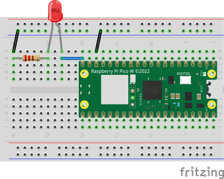
On a breadboard, connect the anode (the longer leg) of an LED to the Pico W's GPIO15 pin. Then connect the cathode (the shorter leg), via a 220 Ω resistor, to GND. The circuit should look like this:
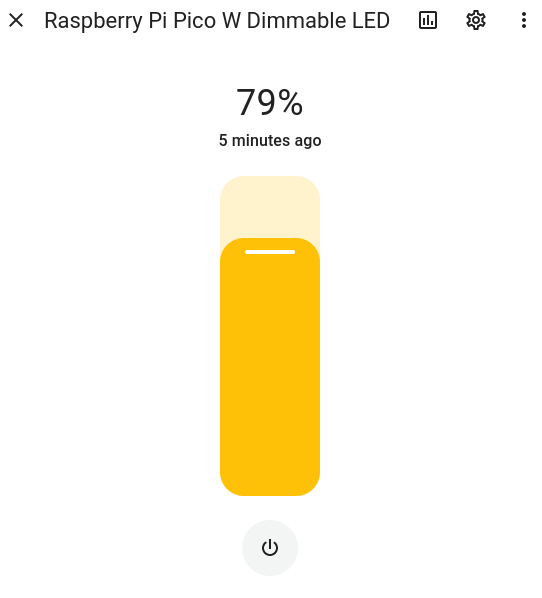
After uploading this firmware to your board, you can control the LED's brightness using Home Assistant's dashboard:
You can also use a PWM output to create various light effects. This is how you define a slow pulse effect that continuously pulses the LED:
output:
  - platform: rp2040_pwm
    pin: 15
    id: led

light:
  - platform: monochromatic
    output: led
    id: pulsating_led
    effects:
      - pulse:
          name: "Slow pulse"
          transition_length: 2s
          update_interval: 2s
To start this effect, add the following automation to the on_boot section of the esphome core configuration:
esphome:
  name: raspberry-pi-pico-w
  friendly_name: Raspberry Pi Pico W
  on_boot:
    then:
      - light.turn_on:
          id: pulsating_led
          effect: "Slow pulse"
After uploading the firmware to the board, the LED will start slowly pulsing.
Only use I2C0
When using I²C devices with the RP2040, it's important to note that ESPHome's I²C component for the RP2040 only works for the i2c0 bus. To determine which pins to use for I²C, always refer to the Raspberry Pi Pico W's pinout:

Only the pins defined as I2C0 SDA and I2C0 SCL can be used for I²C communication. This means you can use the following pin combinations for SDA/SCL: GP0/GP1, GP4/GP5, GP8/GP9, GP12/GP13, GP16/GP17, or GP20/GP21.
Since the GP20/GP21 pins on the Raspberry Pi Pico W are dedicated to I2C0 SDA/I2C0 SCL and do not have any alternative functions, I like to use these pins for the I²C bus. Here's an example configuration to read the temperature, pressure, and humidity from a BME280 sensor board:
i2c:
  sda: 20
  scl: 21

sensor:
  - platform: bme280
    temperature:
      name: "BME280 Temperature"
    pressure:
      name: "BME280 Pressure"
    humidity:
      name: "BME280 Humidity"
    address: 0x77
For some BME280 boards, you need to specify an alternative address, 0x76.
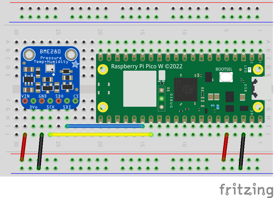
Connect the pins as shown in the following circuit diagram for the BME280:
Driving addressable LED strips
Traditionally, ESPHome supported adressable LED strips using the NeoPixelBus and FastLED platforms for the Light component. However, these platforms don't work with the RP2040. Instead, you can use the RP2040 PIO LED Strip platform, which uses the RP2040 PIO (Programmable Input Output) peripheral to control various addressable LED strips.
For example, an ESPHome configuration to drive a LED strip of eight WS2812B LEDs looks like this:
light:
  - platform: rp2040_pio_led_strip
    name: led_strip
    id: led_strip
    pin: 13
    num_leds: 8
    pio: 0
    rgb_order: GRB
    chipset: WS2812B
Connect the LED strip's DIN to the Pico W's GPIO13, GND to GND, and the LED strip's power pin to VBUS (3V3 isn't enough voltage, while on VBUS there's 5V from the USB connector).
You can now add various light effects to your configuration.
Other RP2040 microcontroller boards
If you look at the configuration file generated by the ESPHome dashboard, by clicking on Edit in the box representing your device, you'll notice the following section for the platform configuration:
rp2040:
  board: rpipicow
  framework:
    # Required until https://github.com/platformio/platform-raspberrypi/pull/36 is merged
    platform_version: https://github.com/maxgerhardt/platform-raspberrypi.git
Since ESPHome uses PlatformIO under the hood, it depends on PlatformIO's support for microcontroller platforms. However, this doesn't support the Raspberry Pi Pico W yet. Max Gerhardt forked PlatformIO's repository and added support for the Raspberry Pi Pico W, as well as other RP2040-based boards.
Initially, I thought that I could just run ESPHome on RP2040 microcontroller boards other than the Raspberry Pi Pico W by specifying a different board name. To test this, I created a new device in the ESPHome dashboard, chose Raspberry Pi Pico W as the device type, and then pressed Skip to not install the firmware immediately to the board. I clicked on Edit in the box representing my device, and changed the board definition rpipicow to another supported board in Max Gerhardt's fork of the RP2040 development platform for PlatformIO, the Arduino Nano RP2040 Connect (arduino_nano_connect). After saving the configuration, I clicked on Install at the top right corner.
However, when I chose Manual download to download the .uf2 file, the image preparation failed, and I encountered several "undefined reference" errors related to the Wi-Fi chip. I should've expected this actually, as the Arduino Nano RP2040 Connect uses the u-blox NINA-W102 instead of the Raspberry Pi Pico W's Infineon CYW43439 for Wi-Fi. The same holds for the Challenger RP2040 WiFi (challenger_2040_wifi), which uses the ESP8285 for Wi-Fi. It seems that additional work on the ESPHome side is required to support these other boards. I don't know any RP2040 boards from other manufacturers than Raspberry Pi using the CYW43439. If they exist, I suspect they should work with ESPHome.
You can still use non-Wi-Fi RP2040 boards this way. For example, here's a configuration for the Seeed Studio XIAO RP2040 (seeed_xiao_rp2040):
esphome:
  name: xiao-rp2040
  friendly_name: Xiao RP2040
  on_boot:
    then:
      - output.turn_on:
          id: led_rgb_enable
      - light.turn_on:
          id: led_rgb
          effect: "Random colors"

rp2040:
  board: seeed_xiao_rp2040
  framework:
    # Required until https://github.com/platformio/platform-raspberrypi/pull/36 is merged
    platform_version: https://github.com/maxgerhardt/platform-raspberrypi.git

# Enable logging
logger:

output:
  - platform: gpio
    pin: 11
    id: led_rgb_enable

light:
  - platform: rp2040_pio_led_strip
    id: led_rgb
    pin: 12
    num_leds: 1
    pio: 0
    rgb_order: GRB
    chipset: WS2812
    effects:
      - random:
          name: "Random colors"
          transition_length: 1s
          update_interval: 1s
The board has a WS2812 RGB LED connected to GPIO12, so you can address it using the rp2040_pio_led_strip platform with num_leds set to 1. The light component also defines a light effect with random colors. But before you can use the RGB LED on this board, you need to set GPIO11 high, so that's what the output component is for. On boot, we first enable the LED, and then start the light effect.
Even if a board isn't supported yet by Max Gerhardt's repository, you can still use it with ESPHome by specifying the board as rpipico (or rpipicow if you find a board with the CYW43439 Wi-Fi chip). This will probably work if you're not doing anything exotic. As an example, this is a configuration for Pimoroni's Tiny 2040 board:
esphome:
  name: tiny-2040
  friendly_name: Tiny 2040
  on_boot:
    then:
      - light.turn_on:
          id: led_rgb
          effect: "Random colors"

rp2040:
  board: rpipico
  framework:
    # Required until https://github.com/platformio/platform-raspberrypi/pull/36 is merged
    platform_version: https://github.com/maxgerhardt/platform-raspberrypi.git

# Enable logging
logger:

output:
  - platform: rp2040_pwm
    id: led_red
    pin: 18
    inverted: True
  - platform: rp2040_pwm
    id: led_green
    pin: 19
    inverted: True
  - platform: rp2040_pwm
    id: led_blue
    pin: 20
    inverted: True

light:
  - platform: rgb
    id: led_rgb
    red: led_red
    green: led_green
    blue: led_blue
    effects:
      - random:
          name: "Random colors"
          transition_length: 1s
          update_interval: 1s
The board has an RGB LED, which the R, G, and B components connected active low (that's why each output definition has inverted: True) to GPIO18, GPIO19, and GPIO20, respectively. This configuration creates a PWM output for each color component, combines them into one RGB light, and starts a light effect with random colors on boot.
Conclusion
In conclusion, the support for the RP2040 platform in ESPHome is not as mature as the support for ESP32 or ESP8266. It lacks the same level of testing and comprehensive documentation. There are several issues reported, and certain functionalities such as MQTT and Bluetooth Low Energy are not yet supported on the RP2040.
However, for a lot of tasks, ESPHome on the Raspberry Pi Pico W is still quite usable. If you have a spare Raspberry Pi Pico W lying around, give it a try! I'm also hopeful that support for additional RP2040 boards with Wi-Fi will be added in the near future.