How to change the default I²C pins in Zephyr
When working with I²C devices in the Zephyr real-time operating system, a lot is configured behind the scenes using a devicetree, a hierarchical data structure that describes available hardware. It took me some time to figure out how to change the default I²C pins (SDA and SCL). Here are my notes.
I tried this with Zephyr's BME280 Humidity and Pressure Sensor sample. My goal was to flash the sample firmware to Nordic Semiconductor's nRF52840 Dongle with a BME280 breakout board.
What are the default I²C pins?
First I needed to find out the default I²C pins. To check this, I looked at the devicetree source include file for the nRF52840 Dongle's Pin Control:
koan@tux:~$ less ~/zephyrproject/zephyr/boards/arm/nrf52840dongle_nrf52840/nrf52840dongle_nrf52840-pinctrl.dtsi
The relevant configuration for the i2c0 peripheral is as follows:
i2c0_default: i2c0_default {
        group1 {
                psels = <NRF_PSEL(TWIM_SDA, 0, 26)>,
                        <NRF_PSEL(TWIM_SCL, 0, 27)>;
        };
};

i2c0_sleep: i2c0_sleep {
        group1 {
                psels = <NRF_PSEL(TWIM_SDA, 0, 26)>,
                        <NRF_PSEL(TWIM_SCL, 0, 27)>;
                low-power-enable;
        };
};
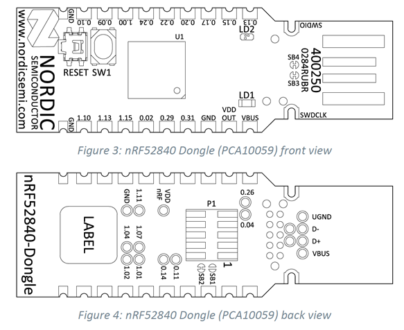
This configures pin 0.26 for SDA and pin 0.27 for SCL. My first thought was to simply connect the BME280 to these pins on the nRF52840 Dongle. However, upon examining the board's pinout, I discovered that pin 0.26 is only exposed as a pad on the bottom, and pin 0.27 isn't accessible anywhere:
How to change the default I²C pins?
Since the default I²C pins weren't suitable on this board, I needed to change them. I decided to connect the BME280 sensor board as follows:
BME280 |
nRF52840 Dongle |
|---|---|
SDA |
0.31 |
SCL |
0.29 |
GND |
GND |
VCC |
VDD |
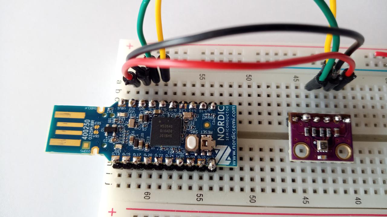
This looks like this on a breadboard:
Next, I copied the sample code so I could change it:
Then, I added a devicetree overlay file called nrf52840dongle_nrf52840.overlay to the project's boards directory. The content of the overlay file is as follows:
/*
 * Configuration of a BME280 device on an I2C bus.
 *
 * Device address 0x76 is assumed. Your device may have a different
 * address; check your device documentation if unsure.
 */
&pinctrl {
        i2c0_default: i2c0_default {
                group1 {
                        psels = <NRF_PSEL(TWIM_SDA, 0, 31)>,
                                <NRF_PSEL(TWIM_SCL, 0, 29)>;
                };
        };

        i2c0_sleep: i2c0_sleep {
                group1 {
                        psels = <NRF_PSEL(TWIM_SDA, 0, 31)>,
                                <NRF_PSEL(TWIM_SCL, 0, 29)>;
                        low-power-enable;
                };
        };
};

&i2c0 {
    status = "okay";
    bme280@76 {
        compatible = "bosch,bme280";
        reg = <0x76>;
    };
};
The &pinctrl section was copied from the devicetree source include file for the nRF52840 Dongle, with pins 26 and 27 changed to 31 and 29, respectively.
The &i2c0 part defines the bme280 sensor with the I²C address 0x76. We need to add this sensor definition here because the nRF52840 Dongle doesn't have it built in.
So, with this overlay, you can use the BME280 sensor connected to pins 0.31 (SDA) and 0.29 (SCL).
Because the file name of the devicetree overlay is the board name nrf52840dongle_nrf52840 with the extension .overlay, Zephyr's build system picks it up automatically if you're building the project for the nRF52840 Dongle and merges it with the default devicetree of the board. If you're building the project for another board, the overlay will be ignored.
Building the code
Let's build the sample code with this devicetree overlay, adding configuration options to initialize USB at boot and enable Zephyr's shell:
koan@tux:~/bme280$ source ~/zephyrproject/zephyr/zephyr-env.sh
koan@tux:~/bme280$ west build -b nrf52840dongle_nrf52840 . -- -DCONFIG_USB_DEVICE_INITIALIZE_AT_BOOT=y -DCONFIG_SHELL=y
Now let's examine the generated devicetree:
This includes the bme280 sensor on the i2c0 bus:
i2c0: i2c@40003000 {
        compatible = "nordic,nrf-twi";
        #address-cells = < 0x1 >;
        #size-cells = < 0x0 >;
        reg = < 0x40003000 0x1000 >;
        clock-frequency = < 0x186a0 >;
        interrupts = < 0x3 0x1 >;
        status = "okay";
        pinctrl-0 = < &i2c0_default >;
        pinctrl-1 = < &i2c0_sleep >;
        pinctrl-names = "default", "sleep";
        bme280@76 {
                compatible = "bosch,bme280";
                reg = < 0x76 >;
        };
};
The Pin Control section shows the I²C pin defaults:
i2c0_default: i2c0_default {
        phandle = < 0x4 >;
        group1 {
                psels = < 0xc001f >, < 0xb001d >;
        };
};
i2c0_sleep: i2c0_sleep {
        phandle = < 0x5 >;
        group1 {
                psels = < 0xc001f >, < 0xb001d >;
                low-power-enable;
        };
};
Here, 1f is of course the hexadecimal representation of 31 and 1d corresponds to 29.
Running the sample
Now that we're confident that the devicetree is correct, let's create a firmware package and flash it to the nRF52840 Dongle:
koan@tux:~/bme280$ nrfutil pkg generate --hw-version 52 --sd-req=0x00 --application build/zephyr/zephyr.hex --application-version 1 bme280.zip

|===============================================================|
|##      ##    ###    ########  ##    ## #### ##    ##  ######  |
|##  ##  ##   ## ##   ##     ## ###   ##  ##  ###   ## ##    ## |
|##  ##  ##  ##   ##  ##     ## ####  ##  ##  ####  ## ##       |
|##  ##  ## ##     ## ########  ## ## ##  ##  ## ## ## ##   ####|
|##  ##  ## ######### ##   ##   ##  ####  ##  ##  #### ##    ## |
|##  ##  ## ##     ## ##    ##  ##   ###  ##  ##   ### ##    ## |
| ###  ###  ##     ## ##     ## ##    ## #### ##    ##  ######  |
|===============================================================|
|You are not providing a signature key, which means the DFU     |
|files will not be signed, and are vulnerable to tampering.     |
|This is only compatible with a signature-less bootloader and is|
|not suitable for production environments.                      |
|===============================================================|

Zip created at bme280.zip
koan@tux:~/bme280$ nrfutil dfu usb-serial -pkg bme280.zip -p /dev/ttyACM0
  [####################################]  100%
Device programmed.
After this, connect to the UART interface over USB:
You should see that the I²C device has been detected, and the sensor values are being displayed:
[00:00:00.317,932] <dbg> BME280: bme280_chip_init: ID OK
[00:00:00.328,582] <dbg> BME280: bme280_chip_init: "bme280@76" OK
*** Booting Zephyr OS build zephyr-v3.4.0-837-gb4ed6c4300a2 ***
Found device "bme280@76", getting sensor data
temp: 25.850000; press: 101.987800; humidity: 59.248046
temp: 25.840000; press: 101.986144; humidity: 59.187500
temp: 25.850000; press: 101.985195; humidity: 59.176757