Flashing a Shelly RGBW2 with crocodile clips and cut resistor leads
The Shelly RGBW2 is a nice Wi-Fi RGBW LED controller. [1] But I want to have open source firmware on as much devices as possible at home. So after playing with the original firmware for a while (for my book about self-hosted home automation) I decided to flash ESPHome on the device.
ESPHome doesn't list the Shelly RGBW2 as an officially supported device, but as it's built around an ESP8266, it should run the firmware fine. It's just a matter of finding the right firmware configuration and the right pins to connect the USB to TTL adapter cable to flash the firmware.
Finding the device pinout isn't an issue. Shelly has extensive documentation about the RGBW2 and neatly shows the pins under the header Flash/Debug:
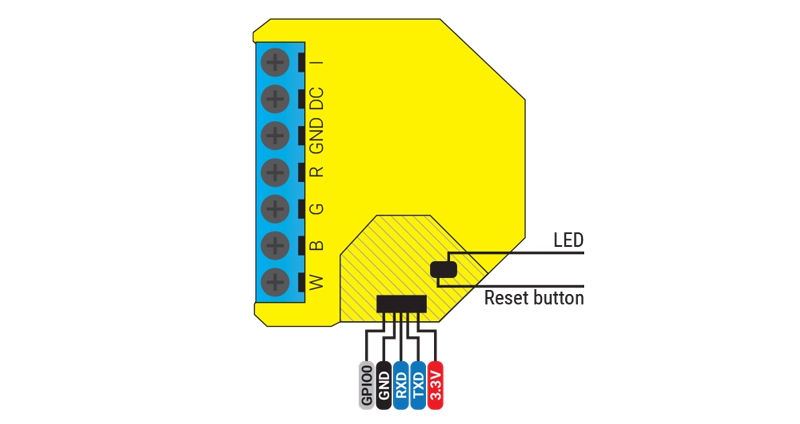
However, connecting to the pin header is something else. While the Shelly 1 has a standard-size 2.54 mm pitch header that fits normal (Dupont) jumper wires, the RGBW2 (as well as the Shelly 2.5) has a 1.27 mm pitch header, which is considerably smaller. So you need some kind of adapter. [2]
I found a number of solutions for this:
The latter looks like the nicest solution, but I had to order the 1.27 mm pitch header and I wanted to flash the device now, so I thought about the easiest way to create an adapter with the stuff I had lying at home.
After giving it some thought, I MacGyvered the following solution:
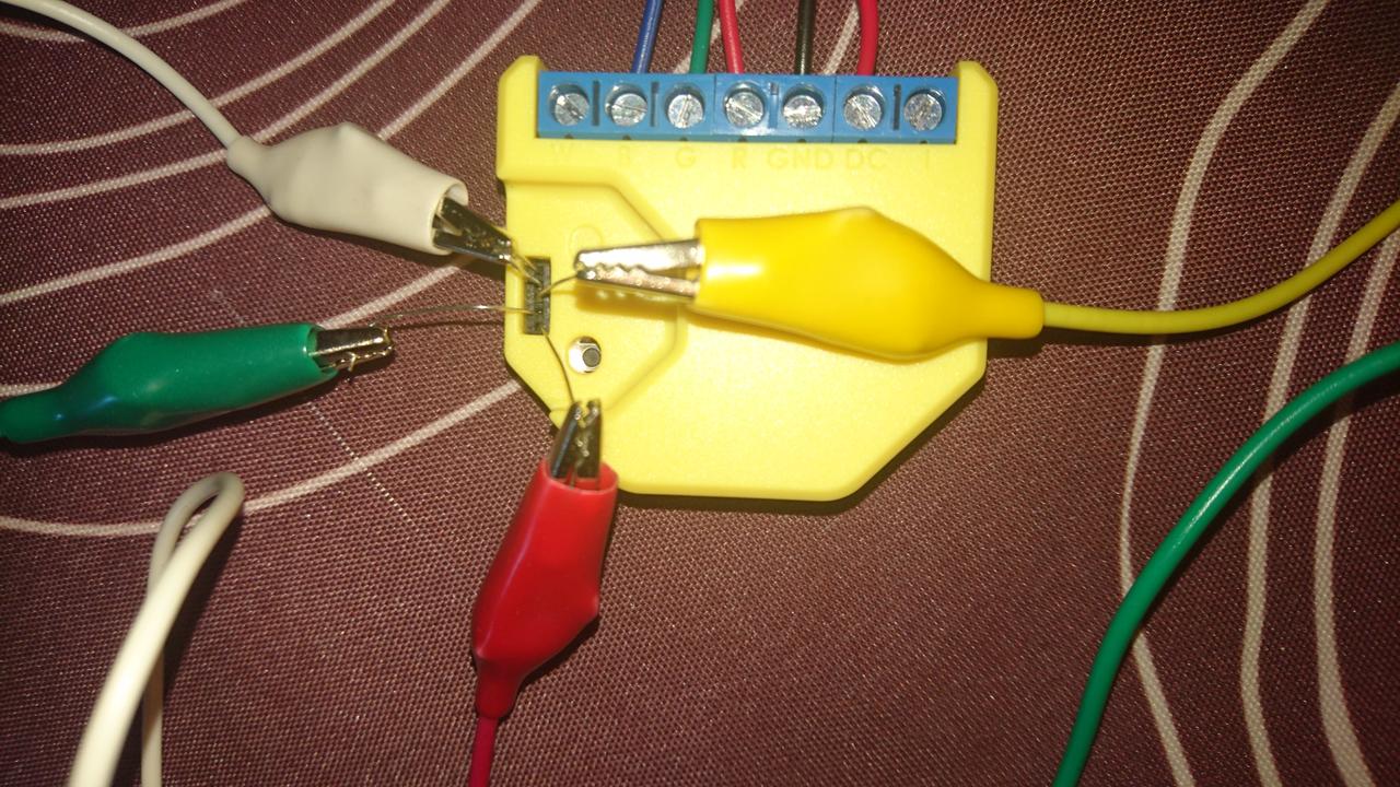
Yes, that's right, these are four crocodile clips and some thin wires put into the header.
The wires are leads I cut off two resistors. This gives you four wires, but you need to connect five pins. However, while flashing you have to pull GPIO0 to ground to start the boot loader in flash mode, so you can just fold one of the resistor leads and put one end in the GPIO0 hole and the other one in the GND hole. The folded wire is then connected to the white crocodile clip you see at the top.
The crocodile clips then connect to jumper wires that go into the breadboard, where the USB to TTL adapter is plugged in, and then connected to my computer to flash the device with the firmware.
This works, but you have to make sure that the resistor leads fit right into the header holes. After some wiggling, the esphome flasher recognized the serial connection, and the result was ESPHome on my RGBW2, which integrates nicely with Home Assistant.
And after this, you can apply OTA (over-the-air) updates of the ESPHome firmware, so you don't need the MacGyver adapter anymore.