Using flat tables in reStructuredText with Sphinx for column and row spans

The reStructuredText markup language has various types of tables. One of these is the list-table, which you create from a two-level bullet list. For instance, this is how you create a list table of the six I/O combinations of Bluetooth Low Energy devices:

.. list-table:: Input and output capabilities
   :header-rows: 1
   :stub-columns: 1

   * -
     - No output
     - Numeric output
   * - No input
     - NoInputNoOutput
     - DisplayOnly
   * - Yes/No
     - NoInputNoOutput
     - DisplayYesNo
   * - Keyboard
     - KeyboardOnly
     - KeyboardDisplay

The first level of bullets lists the rows of the table, while the second level of bullets list the cells in each column of that row. With the header-rows and stub-colums options you specify the number of rows and columns that are rendered in bold.

Sphinx renders this list table like this:

/images/rst-list-table-example.png

I like list tables and I've used them a lot in my books, but they have some limitations. For instance, you can't extend a cell through additional columns or rows. You can create empty cells (like I did in the previous example), but if you would create multiple empty cells next to each other, they aren't merged, but still rendered as separate cells.

Enter the flat-table. This is part of the LinuxDoc extension for Sphinx. [1] A flat table is just like a list table, but with some additional features:

column span

With the role cspan a cell can be extended through additional columns.

row span

With the role rspan a cell can be extended through additional rows.

auto span

The rightmost cell of a table row will automatically be extended over the missing cells on the right side of that table row. With the option fill-cells this behaviour can be changed from auto span to auto fill, which automatically inserts (empty) cells instead of spanning the last cell.

An example:

.. flat-table:: Characteristics of the BLE badge
   :header-rows: 1

   * - Service
     - Characteristic
     - Properties
   * - :rspan:`2` 0xfee7
     - 0xfec7
     - WRITE
   * - 0xfec8
     - INDICATE
   * - 0xfec9
     - READ
   * - 0xfee0
     - 0xfee1
     - NOTIFY, READ, WRITE

Sphinx renders this flat table like this:

/images/rst-flat-table-example.png

As you can see, the cell with 0xfee7 extends through the two next rows, thanks to the :rspan:`2` role. Then in the bullets of the next two rows, you just drop the bullet for the cell that would come on that place. That's why the next two rows only have two bullets, while the last row has three bullets again for the three columns.

If you want to use the flat table with Sphinx, install the linuxdoc Python package:

pip3 install linuxdoc

Then add the extension to the list of extensions in your Sphinx project's conf.py:

extensions = [
  ...
  'linuxdoc.rstFlatTable'
]

After this, you can use the flat-table directive in your reStructuredText files.

Showing a graph on a display with ESPHome

When you create your own sensor devices with ESPHome, you generally let them send their sensor measurements to a home automation gateway such as Home Assistant or an MQTT broker. Then you can visualize these data in a central dashboard.

However, sometimes you want to visualize those data locally on the device itself, on a display. For instance, this year I created an air quality monitor with an ESPHome configuration. The first version just had an RGB LED for local feedback about the measured air quality, but recently I created a second version built around the LilyGO TTGO T-Display ESP32, which has a built-in 1.14 inch display. This way I can display the CO₂ and particulate matter concentrations and the temperature, humidity and pressure locally, which is way more actionable.

ESPHome 2021.10 has a new type of component that is interesting for this purpose: a graph. For instance, this is how I defined the graphs for CO₂ and particulate matter concentrations:

graph:
  - id: co2_graph
    sensor: co2_value
    duration: 1h
    min_value: 400
    max_value: 2000
    width: ${graph_width}
    height: ${graph_height}
    border: false
  - id: pm_graph
    duration: 1h
    min_value: 0
    width: ${graph_width}
    height: ${graph_height}
    border: false
    traces:
      - sensor: pm2_5_value
        color: color_yellow
      - sensor: pm10_value
        color: color_green

Note that the second graph shows multiple sensor values, each in their own colour. There are a lot more options possible, for instance for grids, borders and line types.

Then in your display component you can show these graphs:

display:
  - platform: st7789v
    id: ttgo_tdisplay
    backlight_pin: GPIO4
    cs_pin: GPIO5
    dc_pin: GPIO16
    reset_pin: GPIO23
    rotation: 270
    pages:
      - id: page1
        lambda: |-
          it.graph(0, 60, id(co2_graph));
      - id: page2
        lambda: |-
          it.graph(0, 60, id(pm_graph));

This draws both graphs on their own page, at position x=0, y=60. With a header, frame and some extra information this looks like this on the T-Display's display:

/images/esphome-graph-co2.png

You can find the full configuration in the example file t-display_example.yaml of the GitHub repository of the project.

How to use the Digispark with micronucleus bootloader in the Arduino IDE

The Digispark USB development board is a compact board with the ATtiny85 AVR microcontroller. You can use it in the Arduino IDE by adding http://digistump.com/package_digistump_index.json as an additional board support URL in File / Preferences next to Additional Boards Manager URLs.

After this, open the menu Tools / Board / Boards Manager... and install the package Digistump AVR Boards:

/images/arduino-digistump-avr-boards.png

The Digispark is now supported, but the board support package installs an older version of the command-line tool micronucleus for the bootloader. This is incompatible with newer versions of the bootloader. If you've upgraded the micronucleus bootloader on your Digispark, you need to upgrade the command-line tool too.

So make a backup of the original file and copy the newer micronucleus binary that you installed earlier:

cd ~/.arduino15/packages/digistump/tools/micronucleus/2.0a4/
mv micronucleus micronucleus.original
cp /usr/local/bin/micronucleus .

Now you can flash your Arduino sketches to the device. Try it with one of the example sketches, such as the one in File / Examples / Digispark_Examples / Start. This has the following code that blinks the Digispark's LED:

// the setup routine runs once when you press reset:
void setup() {
  // initialize the digital pin as an output.
  pinMode(0, OUTPUT); //LED on Model B
  pinMode(1, OUTPUT); //LED on Model A  or Pro
}

// the loop routine runs over and over again forever:
void loop() {
  digitalWrite(0, HIGH);   // turn the LED on (HIGH is the voltage level)
  digitalWrite(1, HIGH);
  delay(1000);               // wait for a second
  digitalWrite(0, LOW);    // turn the LED off by making the voltage LOW
  digitalWrite(1, LOW);
  delay(1000);               // wait for a second
}

Then choose the board Digispark (Default - 16.5mhz) in the menu Tools / Board / Digistump AVR Boards and compile the code. If you click on the upload button after this, the Arduino IDE asks you to put the Digispark in a USB port. If all goes well, it uploads the firmware to your board with the newer version of the micronucleus command. And finally the LED on the board starts blinking.

Connecting to Bluetooth Low Energy devices in ESPHome

Bluetooth Low Energy (BLE) devices have two ways to transfer data:

  • Connectionless: This is called "broadcasting" or "advertising": the device advertises its existence, its capabilities and some data, and every BLE device in the neighbourhood can pick this up.

  • With a connection: This requires the client device to connect to the server device and ask for the data.

Until recently, ESPHome only supported reading BLE data without a connection. In my book, I gave some examples about how to use this functionality. I also referred to pull request #1177 by Ben Buxton, which was only merged in ESPHome 1.18.0, after the book was published.

In this blog post, I'll show you how to read the battery level and button presses from a Gigaset keeper Bluetooth tracker, as well as the heart rate of a heart rate sensor, for instance in your fitness tracker.

Setting up a BLE client

If you want your ESPHome device to connect to another device using BLE, you first need to add a ble_client component, which requires an esp32_ble_tracker component. For instance:

esp32_ble_tracker:

ble_client:
  - mac_address: FF:EE:DD:CC:BB:AA
    id: gigaset_keeper

Just specify the BLE MAC address of the device you want to connect to, and give it an ID.

Reading a one-byte characteristic

After connecting to the device, you can create a BLE Client sensor to read one-byte characteristics such as the battery level from your device.

Each BLE server (the device you connect to) has various services and characteristics. The Bluetooth Special Interest Group has published a lot of standard services and their characteristics in their Specifications List. So if you want to read a device's battery level, consult the Battery Service 1.0 document. You see that it defines one characteristic, Battery Level, which "returns the current battery level as a percentage from 0% to 100%; 0% represents a battery that is fully discharged, 100% represents a battery that is fully charged."

Each service and characteristic has a UUID. The standard services and characteristics are defined in the Bluetooth SIG's Assigned Numbers specifications. These are 16-bit numbers. For instance, the Battery service has UUID 0x180f and the Battery Level characteristic has UUID 0x2a19. To read this in ESPHome, you add a sensor of the ble_client platform:

sensor:
  - platform: ble_client
    ble_client_id: gigaset_keeper
    name: "Gigaset keeper battery level"
    service_uuid: '180f'
    characteristic_uuid: '2a19'
    notify: true
    icon: 'mdi:battery'
    accuracy_decimals: 0
    unit_of_measurement: '%'

Make sure to refer in ble_client_id to the ID of the BLE client you defined before.

If you compile this, your ESPHome device connects to your Bluetooth tracker and subscribes to notifications for the battery level. [1]

The Gigaset keeper has another one-byte characteristic that's easy to read, but it's not a standard one: the number of clicks on the button. By exploring the characteristics with nRF Connect, clicking the button and reading their values, you'll find the right one. You can then read this in ESPHome with:

sensor:
  - platform: ble_client
    ble_client_id: gigaset_keeper
    name: "Gigaset keeper button clicks"
    service_uuid: '6d696368-616c-206f-6c65-737a637a796b'
    characteristic_uuid: '66696c69-7020-726f-6d61-6e6f77736b69'
    notify: true
    accuracy_decimals: 0

Every time you click the button on the Gigaset keeper, you'll get an update with the click count. Of course you're probably not interested in the number of clicks, but just in the event that a click happens. You can act on the click with an on_value automation in the sensor, which can for instance toggle a switch in Home Assistant. This way you can use your Bluetooth tracker as a wireless button for anything you want.

Reading arbitrary characteristic values

In ESPHome 1.18 you could only read the first byte of a characteristic, and it would be converted to a float number. In ESPHome 1.19, David Kiliani contributed a nice pull request (#1851) that allows you to add a lambda function to parse the raw data. All received bytes of the characteristic are passed to the lambda as a variable x of type std::vector<uint8_t>. The function has to return a single float value.

You can use this for example to read the value of a heart rate sensor. If you read the specification of the Heart Rate Service, you'll see that the Heart Rate Measurement characteristic is more complex than just a number. There's a byte with some flags, the next one or two bytes is the heart rate, and then come some other bytes. So if you have access to the full raw bytes of the characteristic, you can read the heart rate like this:

sensor:
  - platform: ble_client
    ble_client_id: heart_rate_monitor
    id: heart_rate_measurement
    name: "${node_name} Heart rate measurement"
    service_uuid: '180d'  # Heart Rate Service
    characteristic_uuid: '2a37'  # Heart Rate Measurement
    notify: true
    lambda: |-
      uint16_t heart_rate_measurement = x[1];
      if (x[0] & 1) {
          heart_rate_measurement += (x[2] << 8);
      }
      return (float)heart_rate_measurement;
    icon: 'mdi:heart'
    unit_of_measurement: 'bpm'

Note how the heart rate is in the second byte (x[1]), and if the rightmost bit of x[0] is set, the third byte holds the most significant byte of the 16-bit heart rate value.

However, this way you can still only return numbers. What if you want to read a string? For instance, the device name is accessible in characteristic 0x2a00. Luckily, there's a trick. First define a template text sensor:

text_sensor:
  - platform: template
    name: "${node_name} heart rate sensor name"
    id: heart_rate_sensor_name

And then define a BLE client sensor that accesses the raw bytes of the Device Name characteristic, converts it to a string and publishes it to the template text sensor:

sensor:
  - platform: ble_client
    ble_client_id: heart_rate_monitor
    id: device_name
    service_uuid: '1800'  # Generic Access Profile
    characteristic_uuid: '2a00'  # Device Name
    lambda: |-
      std::string data_string(x.begin(), x.end());
      id(heart_rate_sensor_name).publish_state(data_string.c_str());
      return (float)x.size();

The only weirdness is that you need to return a float in the lambda, because it's a sensor that's expected to return a float value.

After someone on the Home Assistant forum asked how he could read the heart rate of his BLE heart rate monitor, I implemented all this in a project that displays the heart rate and device name of a BLE heart rate sensor on an M5Stack Core or LilyGO TTGO T-Display ESP32, my two go-to ESP32 boards. I published the source code on GitHub as koenvervloesem/ESPHome-Heart-Rate-Display.

This looks like this:

/images/esphome-heart-rate-display-m5stack-core.jpg

This is just one example of the many new possibilities with Bluetooth Low Energy in ESPHome 1.19.

How to build AVR code for the Digispark with PlatformIO

PlatformIO supports the Digispark USB development board, a compact board with the ATtiny85 AVR microcontroller. The canonical example code that lets the built-in LED blink looks like this:

digispark_blink_platformio/main.c (Source)

/* Atml AVR native blink example for the Digispark
 *
 * Copyright (C) 2021 Koen Vervloesem (koen@vervloesem.eu)
 *
 * SPDX-License-Identifier: MIT
 */
#include <avr/io.h>
#include <util/delay.h>

// Digispark built-in LED
// Note: on some models the LED is connected to PB0
#define PIN_LED PB1
#define DELAY_MS 1000

int main(void) {
  // Initalize LED pin as output
  DDRB |= (1 << PIN_LED);

  while (1) {
    PORTB ^= (1 << PIN_LED);
    _delay_ms(DELAY_MS);
  }

  return 0;
}

If you've bought your Digispark recently, the Micronucleus bootloader is a recent version that isn't supported by PlatformIO's older micronucleus command.

If you've already upgraded the bootloader on your Digispark, you also have the newest version of the micronucleus command. So the only thing you need is make PlatformIO use this version when uploading your code. You can do this with the following platformio.ini:

[env:digispark-tiny]
platform = atmelavr
board = digispark-tiny
upload_protocol = custom
upload_command = micronucleus --run .pio/build/digispark-tiny/firmware.hex

The platform and board options are just the configuration options the PlatformIO documentation lists for the Digispark USB. By setting the upload_protocol to custom, you can supply your own upload command, and the micronucleus in this command refers to the one you've installed globally with sudo make install in /usr/local/bin/micronucleus. [1]

After this, you can just build the code and upload it:

koan@tux:~/digispark_blink_platformio$ pio run -t upload
Processing digispark-tiny (platform: atmelavr; board: digispark-tiny)
---------------------------------------------------------------------------------------------------------
Verbose mode can be enabled via `-v, --verbose` option
CONFIGURATION: https://docs.platformio.org/page/boards/atmelavr/digispark-tiny.html
PLATFORM: Atmel AVR (3.1.0) > Digispark USB
HARDWARE: ATTINY85 16MHz, 512B RAM, 5.87KB Flash
DEBUG: Current (simavr) On-board (simavr)
PACKAGES:
 - tool-avrdude 1.60300.200527 (6.3.0)
 - toolchain-atmelavr 1.50400.190710 (5.4.0)
LDF: Library Dependency Finder -> http://bit.ly/configure-pio-ldf
LDF Modes: Finder ~ chain, Compatibility ~ soft
Found 0 compatible libraries
Scanning dependencies...
No dependencies
Building in release mode
Checking size .pio/build/digispark-tiny/firmware.elf
Advanced Memory Usage is available via "PlatformIO Home > Project Inspect"
RAM:   [          ]   0.0% (used 0 bytes from 512 bytes)
Flash: [          ]   1.4% (used 82 bytes from 6012 bytes)
Configuring upload protocol...
AVAILABLE: custom
CURRENT: upload_protocol = custom
Uploading .pio/build/digispark-tiny/firmware.hex
> Please plug in the device ...
> Device is found!
connecting: 33% complete
> Device has firmware version 2.5
> Device signature: 0x1e930b
> Available space for user applications: 6650 bytes
> Suggested sleep time between sending pages: 7ms
> Whole page count: 104  page size: 64
> Erase function sleep duration: 728ms
parsing: 50% complete
> Erasing the memory ...
erasing: 66% complete
> Starting to upload ...
writing: 83% complete
> Starting the user app ...
running: 100% complete
>> Micronucleus done. Thank you!
====================================== [SUCCESS] Took 3.99 seconds ======================================

I've created a GitHub project with this configuration, the example code, a Makefile and a GitHub Action to automatically check and build the code: koenvervloesem/digispark_blink_platformio. This can be used as a template for your own AVR code for the Digispark with PlatformIO.

How to upgrade the micronucleus bootloader on the Digispark

The Digispark USB development board has an ATtiny85 microcontroller. (source: Digistump)

Recently I have been playing with the Digispark development board with the ATtiny85 AVR microcontroller. The cool thing is that it's only 2 by 2 cm big and it plugs right into a USB port.

But when I flashed the canonical blink example to the microcontroller, I noticed that the program didn't blink continuously with the fixed interval I had set up. The first five seconds after plugging in the Digispark the LED blinked in a fast heartbeat pattern (which seems to be normal, this is the bootloader staying in the programming mode for five seconds), then my program slowly blinked for a few seconds, then it was five seconds in heartbeat pattern again, then slower blinks again, and so on. It seemed the microcontroller got stuck in a continuous boot loop.

Thinking about the previous time I solved a microcontroller problem by upgrading the bootloader, I decided to try the same approach here. The Digispark is sold with the Micronucleus bootloader, but the boards I bought [1] apparently had an older version. Upgrading the bootloader is easy on Ubuntu.

First build the micronucleus command-line tool:

git clone https://github.com/micronucleus/micronucleus.git
cd micronucleus/commandline
sudo apt install libusb-dev
make
sudo make install

The Micronucleus project offers firmware files to upgrade older versions, so then upgrading the existing firmware was as easy as:

cd ..
micronucleus --run firmware/upgrades/upgrade-t85_default.hex

Then insert the Digispark to write the firmware.

After flashing the blink example, I didn't see the boot loop this time. And the Micronucleus developers apparently got rid of the annoying heartbeat pattern in the newer version.

Change the uplink interval of a Dragino LoRaWAN sensor

I have a couple of Dragino's LoRaWAN temperature sensors in my garden. [1] The LSN50 that I bought came with a default uplink interval of 30 seconds. Because the temperature outside doesn't change that fast and I want to have a long battery life, I wanted to change the uplink interval to 10 minutes.

Dragino's firmware accepts commands as AT commands over a USB to TTL serial line (you need to physically connect to the device's UART pins for that) or as LoRaWAN downlink messages (which you can send over the air via the LoRaWAN gateway). All Dragino LoRaWAN products support a common set of commands explained in the document End Device AT Commands and Downlink Commands.

The Change Uplink Interval command starts with the command code 0x01 followed by three bytes with the interval time in seconds. So to set the uplink interval to 10 minutes, I first convert 600 seconds to its hexadecimal representation:

$ echo 'ibase=10;obase=16;600' | bc
258

So I have to send the command 0x01000258.

My LoRaWAN gateway is connected to The Things Network, a global open LoRaWAN network. You can send a downlink message on the device's page in The Things Network's console (which is the easiest way), but you can also do it with MQTT (which is a bit harder). The Things Network's MQTT API documentation shows you the latter. [2] The MQTT topic should be in the form <AppID>/devices/<DevID>/down and the message looks like this:

{
  "port": 1,
  "confirmed": false,
  "payload_raw": "AQACWA=="
}

Note that you should supply the payload in Base64 format. You can easily convert the hexadecimal payload to Base64 on the command line:

$ echo 01000258|xxd -r -p|base64
AQACWA==

Enter this as the value for the payload_raw field.

So then the full command to change the uplink interval of the device to 10 minutes becomes:

$ mosquitto_pub -h eu.thethings.network -p 8883 --cafile ttn-ca.pem -u AppID -P AppKey -d -t 'AppID/devices/DevID/down' -m '{"port":1,"payload_raw":"AQACWA=="}'

This downlink message will be scheduled by The Things Network's application server to be sent after the next uplink of the device. After it has been received, the device changes its uplink interval.

Getting started with ESPHome

Last week my new book has been published, Getting Started with ESPHome: Develop your own custom home automation devices. It demonstrates how to create your own home automation devices with ESPHome on an ESP32 microcontroller board.

I always like to look at the big picture. That's why I want to take some time to talk about what ESPHome is, why you should use it and what you need.

Configuring instead of programming

The ESP8266 and its successor, the ESP32, are a series of low-cost microcontrollers with integrated Wi-Fi (for both series) and Bluetooth (for the ESP32), produced by Espressif Systems. The maker community quickly adopted these microcontrollers for tasks where an Arduino didn't suffice. [1]

You can program the ESP8266 and ESP32 using Espressif's ESP-IDF SDK, the ESP32 Arduino core, or MicroPython. Arduino and MicroPython lower the bar significantly, but it still takes some programming experience to build solutions with these microcontrollers.

One of the domains in which the ESP8266 and ESP32 have become popular is in the DIY (do-it-yourself) home automation scene. You just have to connect a sensor, switch, LED, or display to a microcontroller board, program it, and there you have it: your customised home automation device.

However, "program it" isn't that straightforward as it sounds. For instance, if you're using the Arduino environment, which has a lot of easy-to-use libraries, you still have to know your way around C++.

Luckily there are a couple of projects to make it easier to create firmware for ESP8266 or ESP32 devices for home automation. One of these is ESPHome.

On its homepage, the ESPHome developers describe it as: "ESPHome is a system to control your ESP8266/ESP32 by simple yet powerful configuration files and control them remotely through Home Automation systems."

The fundamental idea of ESPHome is that you don't program your ESP8266 or ESP32 device, but configure it. Often you only have to configure which pins you have connected to a component, such as a sensor. You don't have to initialize the sensor, read its values in a loop, and process them.

Configuration is a completely different mindset than programming. It lowers the bar even more. With ESPHome, everyone can make home automation devices. [2]

Essentially ESPHome creates C++ code based on your configuration. The process looks like this:

/images/esphome-yaml-to-firmware.png

So when you write a YAML file with your device's configuration, ESPHome generates C++ code from it. More specifically, ESPHome creates a PlatformIO project using the Arduino framework. PlatformIO then builds the C++ code, and esptool uploads the resulting firmware to your device.

You don't have to know anything about what's happening under the hood. You just have to write the configuration of your device in a YAML file and memorise a small number of commands to let ESPHome do the rest.

The advantages of ESPHome

Why use ESPHome? The first reason is clear from the project's description: because you don't need to be able to program. Even if you're a programmer, ESPHome offers many advantages:

Works completely locally

Many commercial Wi-Fi-based home automation devices need a connection to a cloud service of the manufacturer. In contrast, ESPHome devices work locally and can communicate with a local home automation system such as Home Assistant or an MQTT-based home automation system.

Offers on-device automations

Many home automation systems use a central gateway that contains all the logic, with automations like "if the sun goes down, close the blinds." In contrast, ESPHome offers powerful on-device automations. Your devices can work independently from a home automation gateway, so they keep working if they lose Wi-Fi access or if your home automation gateway crashes.

Offers over-the-air updates

ESPHome includes out-of-the-box over-the-air (OTA) update functionality. This makes it easy to centrally manage your ESPHome devices and update the firmware. This means you don't have to go around your house with your laptop to connect a serial cable to each device and flash the firmware.

Supports a lot of components

ESPHome supports many components out-of-the-box: several types of sensors, switches, and displays (even e-paper displays) are available with just a couple of configuration lines. The list of supported components is growing with every release.

Has extensive documentation

The developers have documented every component in ESPHome, and this documentation is quite good.

Is customisable

Although you create ESPHome firmware by writing a configuration file, ESPHome doesn't hide anything from you. It's still possible to add custom components that you write in C++. You can even look at the C++ code that ESPHome generates and change it.

What hardware do you need?

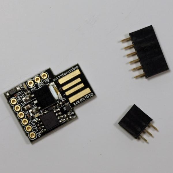
ESPHome creates custom firmware for the ESP8266 and ESP32 microcontrollers, so you need one of these. There are many types of boards for both microcontrollers, varying in the amount of flash memory, RAM, and available pins. Some of them even come with extras such as a built-in display (OLED, TFT, or e-paper), battery, or camera.

ESPHome doesn't support all features of all boards out-of-the-box. Technically, all ESP8266/ESP32 devices should be able to run ESPHome. Some features just aren't supported yet.

Your first choice is between the ESP8266 or ESP32. If you're buying a device at present, the choice is simple: the ESP32. It is much more capable than its predecessor and has a faster processor, more memory, more peripherals, and adds Bluetooth.

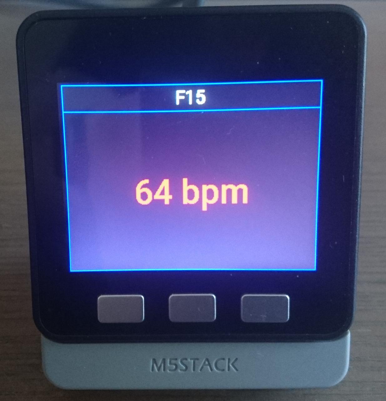
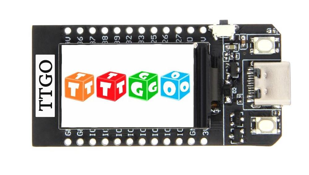
Then comes the choice of board. Espressif has some development boards. Many other companies are making them too. There are even complete kits such as the M5Stack series. These are ESP32 development boards ready to use in your living room in a case with a display, buttons, MicroSD card slot, and speaker. These are currently my favourite devices to use with ESPHome. If you don't need something with a nice finish as the M5Stack devices, the TTGO T-Display ESP32 made by LilyGO is my development board of choice: it has an integrated 1.14 inch TFT display.

/images/ttgo-t-display.jpg

Other interesting devices to run ESPHome on are devices from manufacturers such as Sonoff and Shelly. These come with firmware that works with the manufacturer's cloud services. You can however replace the firmware with ESPHome. This unlocks the full potential of these devices and lets you use them in your local home automation system without any link to a cloud system.

What software do you need?

You can use ESPHome to create a fully autonomous microcontroller project --- for example, a plant monitor that turns on an LED if the plant's soil is too dry. However, if you don't publish the plant's status over the network, this would be a waste of the ESP32's capabilities. The main usage cases of ESPHome are:

  • To send a device's sensor measurements to a home automation gateway.

  • To remotely control a device's lights or switches from a home automation gateway.

ESPHome supports two ways of communication between your device and the home automation gateway:

Native API

The ESPHome native API is a highly optimised network protocol using Google's protocol buffers. It's meant to be used with Home Assistant --- a popular open-source home automation system.

MQTT

MQTT (Message Queuing Telemetry Transport) is an OASIS standard messaging protocol designed with a lightweight publish/subscribe approach for messages. All your ESPHome devices then communicate with an MQTT broker such as Eclipse Mosquitto.

From the beginning (when it was still called esphomeyaml), the ESPHome project has been tightly integrated with Home Assistant, so the ESPHome developers prefer the native API. However, MQTT is fully supported, allowing your devices to communicate with many other home automation gateways, as MQTT is a popular standard. [3]

Do you need a development environment?

With ESPHome you don't program your devices but configure them. However, you still need something that looks like a "development" environment. When your device configurations are simple, you could do without, but the more complex they become, you'll need all the help you can get.

This doesn't mean you have to install a full-blown Integrated Development Environment (IDE). You should only need a couple of programs:

An editor

You could make do with a simple text editor such as Notepad (Windows), TextEdit (macOS), or the default text editor on your Linux distribution. However, having an editor with syntax highlighting for YAML files is easier. Some examples are Notepad++ and Sublime Text. If you're a command-line user on Linux, both vim and Emacs work fine. [4] Use whatever you like, because your editor is an important tool to work with ESPHome.

A YAML linter

A linter is a program that checks your file for the correct syntax. An editor with syntax highlighting has this linter built-in, but you can also run this standalone. A good YAML linter is the Python program yamllint. Not only does it check for syntax validity, but also weird things like key repetitions, as well as cosmetic problems such as line length, trailing spaces, and inconsistent indentation. ESPHome includes its own linter, specifically targeted at finding errors in ESPHome configurations. Both linters are complementary.

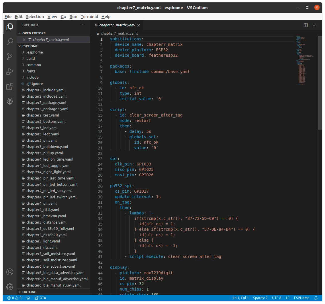
If you're used to developing in an IDE, an interesting alternative is the ESPHome plugin for Visual Studio Code. [5] This plugin provides validation and completion of what you type in an ESPHome YAML file. It also shows tooltips with help when you hover over keywords in the configuration.

/images/esphome-vscode-plugin.png

Building ESP32 firmware with Espressif's IDF Docker image

If you're only occasionally building ESP32 firmware with Espressif's IoT Development Framework (ESP-IDF), your current build probably fails because the installation from last time is outdated. Then you have to reinstall the newest version of the framework and its dependencies, and you probably still encounter a dependency issue. If it finally works and you have successfully built your firmware, your excitement makes up for the frustrating experience, until the next time you want to build some other ESP32 firmware, and the process repeats.

But there's another way: use the IDF Docker image. It contains ESP-IDF, all the required Python packages, and all build tools such as CMake, make, ninja, and cross-compiler toolchains. In short: a ready-to-use IDF build system.

Building ESP32 firmware with CMake in the container is as easy as:

docker run --rm -v $PWD:/project -w /project espressif/idf idf.py build

This mounts the current directory on the host ($PWD) as the directory /project in the container and runs the command idf.py build on the code. After the build is finished, you can find your firmware in the current directory.

The same works if the project is using make for its build:

docker run --rm -v $PWD:/project -w /project espressif/idf make defconfig all -j4

You can also use the container interactively.

How to upgrade the Adafruit nRF52 bootloader

The Adafruit nRF52 bootloader is a USB-enabled CDC/DFU/UF2 bootloader for nRF52 boards. An advantage compared to Nordic Semiconductor's default bootloader is that you can just drag and drop your application firmware from your operating system's file explorer, without having to install any programming tools. For nRF52840 boards, you hold the reset button while sliding the USB connector in the USB port of your computer, or you tap the reset button twice within 500 ms. The bootloader then starts in DFU (device firmware upgrade) mode and behaves like a removable flash drive.

This device shows three virtual files:

INFO_UF2.TXT

contains information about the bootloader build and the board on which it's running

INDEX.HTM

redirects to a page that contains an IDE or other information about the board

CURRENT.UF2

the contents of the entire flash storage of the device

Flashing the device with new firmware is as easy as copying a UF2 file to the drive. After the file is copied, the drive is unmounted and the new firmware is running on the board. [1]

However, the bootloader itself can't be upgraded like this. Today I had some problems with the April USB Dongle 52840 [2] that interrupted the UF2 file transfer before it was finished. The dmesg command showed a call trace and some errors. As a result, the device was useless: I couldn't put any new firmware on it.

I was puzzled, but then I looked at the bootloader's version in INFO_UF2.TXT, and this was quite old: a 0.2.x version from 2018. I hoped that upgrading the bootloader would solve the problem.

Upgrading the Adafruit nRF52 bootloader is quite easy:

  1. Download the latest release of the bootloader. For the April USB Dongle 52840 and other devices based on Nordic Semiconductor's nRF52840 Dongle [3], the firmware file is pca10059_bootloader-0.5.0.zip for the bootloader and SoftDevice wireless protocol stack. PCA10059 is the official name of Nordic Semiconductor's nRF52840 Dongle.

  2. Unpack the ZIP file. You need the file pca10059_bootloader-0.5.0_s140_6.1.1.zip (yes, another ZIP file) in it.

  3. Install adafruit-nrfutil: pip3 install --user adafruit-nrfutil.

  4. Connect the board to your computer's USB port and flash the new bootloader package:

$ adafruit-nrfutil dfu serial --package pca10059_bootloader-0.5.0_s140_6.1.1.zip --port /dev/ttyACM0
Upgrading target on /dev/ttyACM0 with DFU package /home/koan/pca10059_bootloader-0.5.0_s140_6.1.1.zip. Flow control is disabled, Dual bank, Touch disabled
########################################
########################################
########################################
########################################
########################################
########################################
########################################
########################################
########################################
############
Activating new firmware
Device programmed.

After this, the INFO_UF2.TXT file contains UF2 Bootloader 0.5.0 lib/nrfx (v2.0.0) lib/tinyusb (0.9.0-22-g7cdeed54) lib/uf2 (remotes/origin/configupdate-9-gadbb8c7).

Luckily the upgraded bootloader solved my problem: I was able to flash the board with new UF2 application firmware.